Building a Laser Show
Lasers have always fascinated me. I love the colours, the power, sometimes the danger, but also the beautiful things you can do when you combine them with some simple optics and mechanics. A ballpoint pen spring with a tiny mirror glued to the top produces some fascinating oscillating patterns when you shine a simple laser pointer at it - imagine what you can do when you introduce digital control and high precision…
Galvanometers are just the ticket. Effectively they move an object proportional to the amount of current flowing through them. The object can be a needle (in the case of gauges or meters) or as I’ll be using, mirrors. With two placed orthogonally (at right-angles), one pivoting a mirror on the X axis, and another on the Y axis, you can reflect the laser beam on both mirrors and produce a coordinate system on a surface such as a wall.
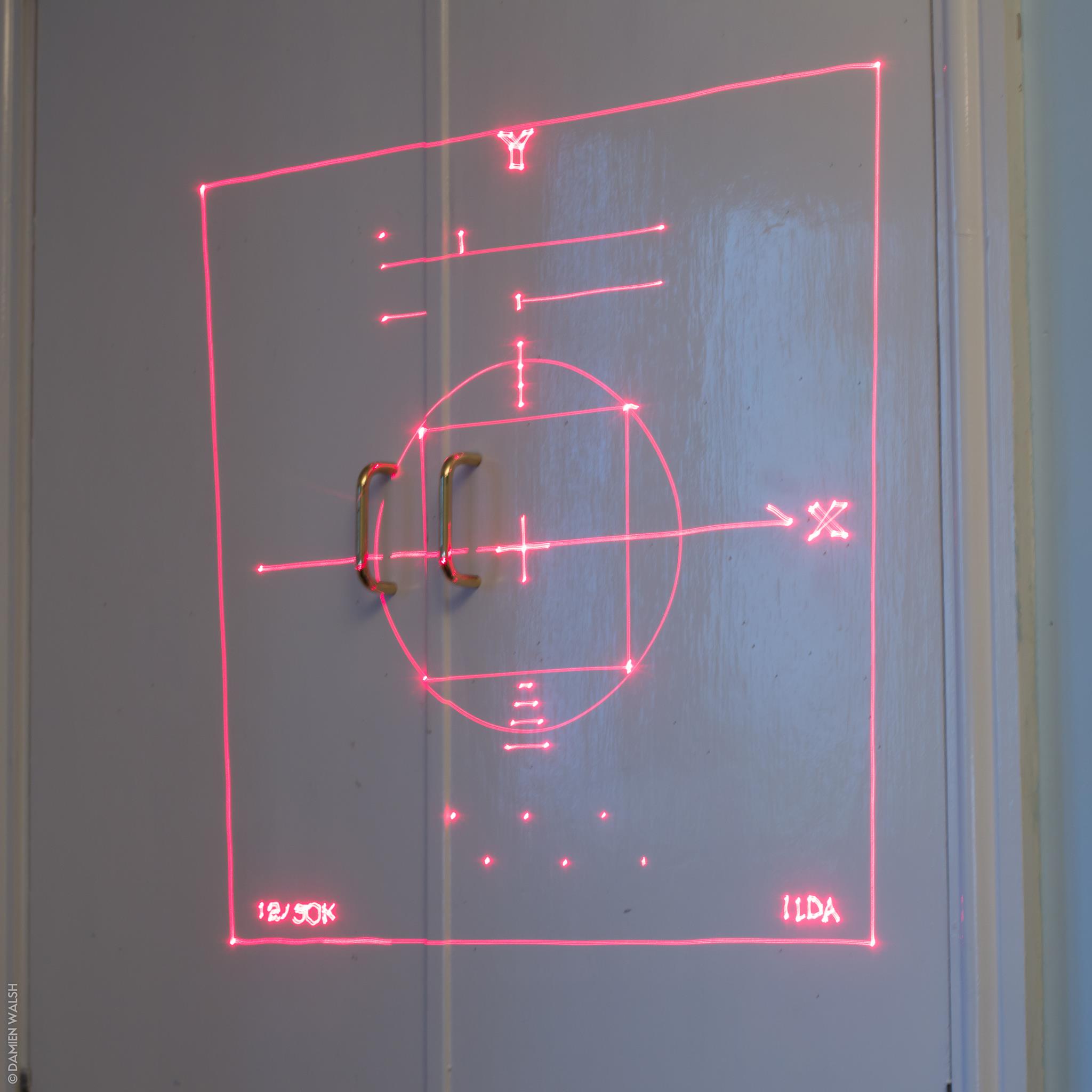
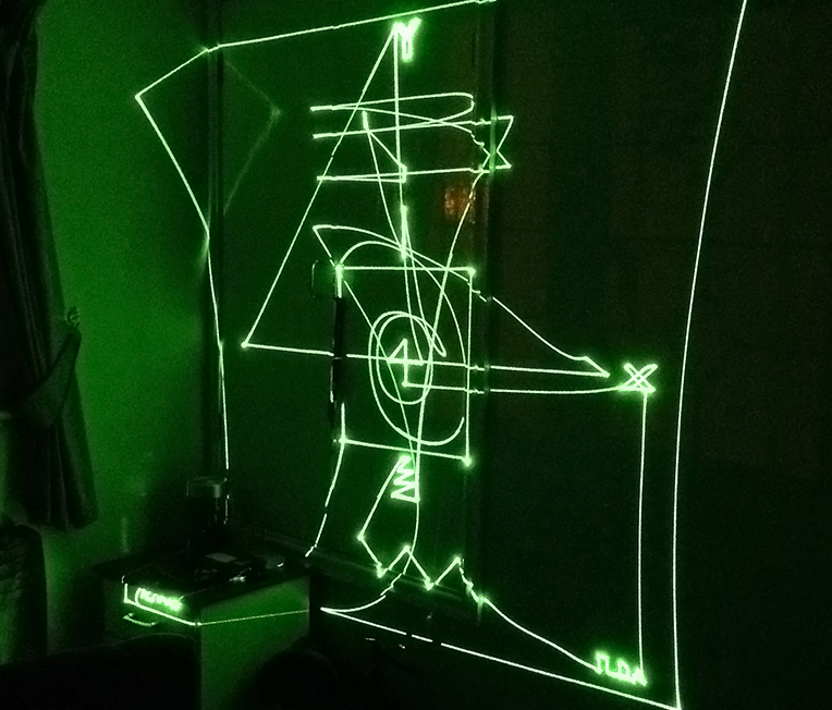
Projecting the ILDA test pattern onto my wall. Still not perfect, there are some tuning tweaks to be made to the galvo driver amplifiers. Here’s what the test pattern should look like.
These things are cheap. Ish. Price point really translates to scan speed, measured in kpps (thousands of points per second). I paid around £70 for a pair of 25kpps galvos and the amplifiers for them, shipped from China of course.
Controlling these is where the real challenge comes.
I’ve put together a little system that works fairly well and I thought I’d blog about it so other people can have a go too! Here goes…
Overview
Here’s how the system will work.
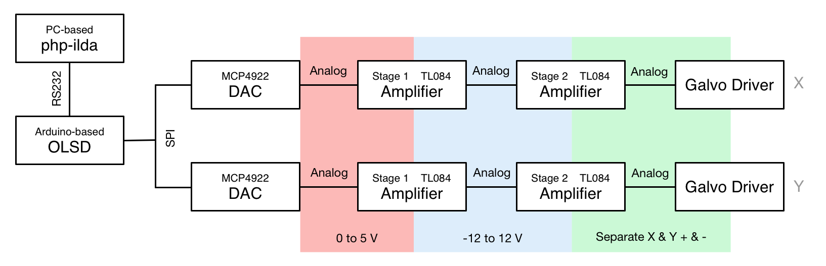
I’ll go through the block diagram section-by-section and explain what part each component plays in generating awesome laser shows.
ILDA, the International Laser Display Association defines a number of standards on the topic of laser shows. One important standard is format of the files that store a show. These files contain “frames” - sets of coordinates for the laser heads to draw and any associated colour information. This standard is specified quite clearly in a document published by IDLA. The first stage of the project was therefore to find a way to decode these files and feed the data into the galvanometer/amplifier setup. As a PHP guy, I used PHP and wrote a few helper classes called php-ilda to manage this, but you could do it any number of ways. I’m currently neatening up the project and generalising the code to make it possible to generate the ILDA data files from inputted data too. For now, I wrote a little class that spits out Arduino code for a given frame. This Arduino code links against a little library that talks to the Dual DAC chip over SPI.
OLSD & Arduino
The Arduino runs a small library called OLSD - The Open Laser Show DAC driver project. It’s a small project that provides an interface to talk to the DACs later on in the system from Arduino code. I based quite a bit of my electronics design on the materials provided with the OLSD library too (thanks again to those guys - fantastic work!) - it’s a very strong setup and works really nicely. The chips used can be swapped out - I couldn’t source the power controller chip specified so had to find an alternative of similar specifications that, with a few decoupling capacitors, works perfectly.
void setup()
{
  // Init the DACs
  dac.Init();

  // Set the output rate to 12kpps
  dac.SetOutputRate(12000);

  // Write out some points
  dac.OutputPoint(42998, 65349, 0, 0, 0);
  dac.OutputPoint(40438, 65361, 0, 0, 0);
  dac.OutputPoint(37879, 65370, 0, 0, 0);
}
Code as simple as this can then be called to direct the laser to the desired coordinates. It’s a great little library and allowed me to avoid working with some of the lower-level Arduino hardware, namely the timers and interrupt handling.
Digital to Analog Converters
The real magic behind this project happens in the DAC (Digital to Analog Converter) chips. They convert digital information - 1s and 0s into voltage levels. The DAC chip I used is the MCP4922 - it’s a Dual DAC, so it’s actually two DACs rolled into one DIL package. The DACs effectively map a range of numbers onto a specific voltage range. These DACs are 12 bit ones, therefore they effectively map a range of numbers from 0 to 4095 onto a voltage range of 0-5V. This is quite precise and is the real driving force behind getting clear, accurate images out of the setup. The DACs talk to the Arduino using the SPI protocol - it’s a simple serial protocol that lets tiny, simple devices talk over a short distance - perfect for this scenario.
Amplification
Another large part of this project is amplification - the analog signal outputted by the DACs is not of sufficient amplitude to drive the galvo drivers directly. Some operational amplifiers (Op Amps) are used to “rescale” the 0-5V provided by the DACs to -12V to +12V. Another pair of operational amplifiers then effectively splits the negative and positive parts of each axis’ (X and Y) analog signal so that they are on separate lines, ready for the galvo drivers. The drivers themselves are effectively amplifiers with more capacity to be tuned, damped and filtered. The tuning process for the setup is quite complex and must be executed precisely and carefully in order to get a good quality projection.
Blanking
Blanking means switching the laser off at the right time. This is crucial to drawing anything that isn’t a simple closed shape. TTL (Transistor-Transistor Logic - effectively 5V for “On” and 0V for “Off”) blanking is supported by a lot of laser modules and you can interface with it using the digital output pins on the Arduino. OLSD has a few methods to control the blanking on your lasers, you should make use of these as they will be faster and better synchronised than using the standard pinMode/digitalWrite Arduino methods.
You can test your rig with blanking disabled or disconnected, or completely absent if your laser doesn’t have that functionality.
Being Careful
This is a reasonably safe thing to build. The real risk is damaging your eyesight with the laser. Wear the correct, good-quality eye protection at all times while the laser is operating. Another top tip is never allow the galvos and laser to be in a position that can direct a static beam your way. A scanning beam is slightly safer, but the real danger is static, still beams, either directly from the laser module or reflected from still mirrors. Make sure that the setup can never direct a beam in this way at either extreme of both the X and Y axis.
Many of the galvo driver rigs available online include a small power supply to provide +15 & -15V DC lines. The DC lines themselves are safe, but the power supplies tend to be cheap and have exposed AC terminals without plastic covers. Do be careful if this affects your power supply.
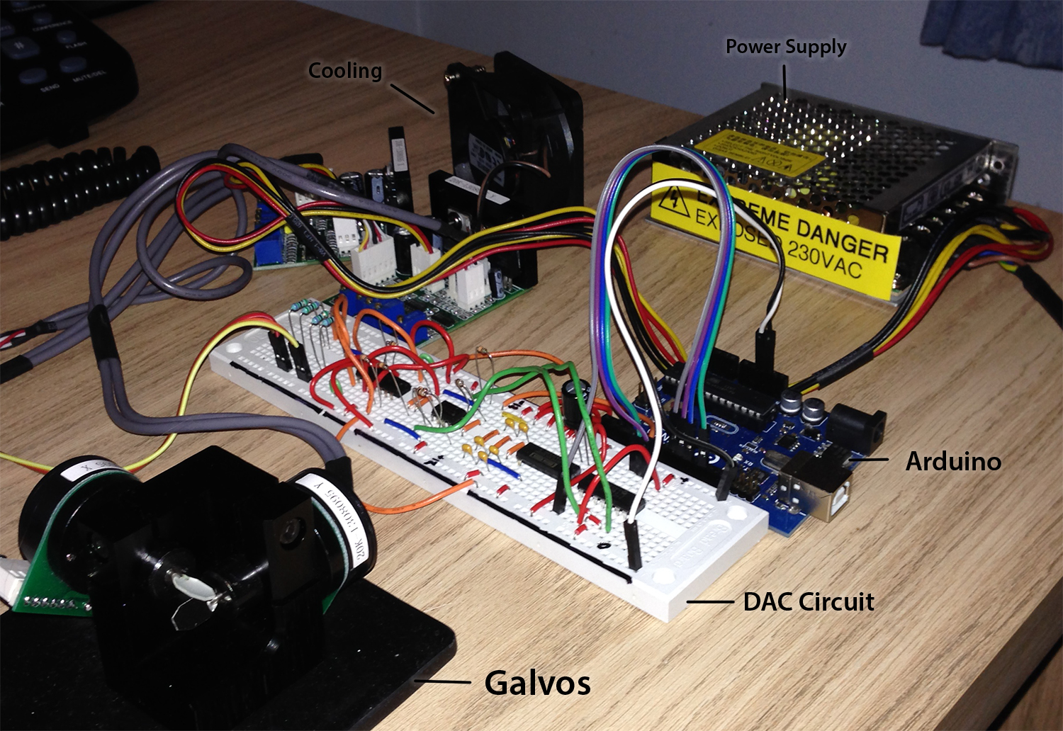
Other than damaging yourself, you also need to look after the kit. The galvanometers are really easy to damage. Handle them carefully to start with, and once you start using them, ensure that both the galvos and their driver MOSFETs are effectively thermally managed - use a heatsink and perhaps some active cooling such as a fan or Peltier element. Take care that you don’t expect too much of the galvanometers - projecting large deflection patterns (I.e. repeatedly having them fling between two coordinates that are far apart) can cause them to overheat, even while mounted in a reasonably good heatsink.
My Ultimate Plan…
I hope to build this into a PCB, perhaps following the OLSD designs again, and also take the leap into RGB, using dichroic glass and two more lasers. But more than that, I want to take the software side of the project further.
Arduino is good, but Raspberry Pi would be cooler. Web interface. Draw your own laser shows and render them in real time. Control the laser dot with the mouse. I have a lot of ideas but work has taken over my life a little at the moment. I’ll be doing a less technical blog post soon about that but for now, enjoy lasering!
Please do comment with your ideas or suggestions too.