Retrofitting Mains Outdoor Lighting
During the wettest months of last year, we started suffering some nuisance tripping of the earth fault protection devices at home (called Ground-Fault Circuit Interrupters - GFCIs - in the US and Residual Current Devices - RCDs - in the UK). When these devices trip and disconnect the power, it normally means that current is leaking away from the live conductors (that’s Line or Neutral) somewhere in the electrical system; which is undesirable. They’re designed principally to protect people against electric shock when these types of fault conditions arise.
The prime suspects when this starts happening are compromise of insulation or ingress of water. The latter is obviously most likely to occur outside.
In our case, that’s precisely what was happening. We have a number of outdoor light fittings that were all suspects for water ingress. I quickly narrowed the cause down to the 5 spotlights mounted in the wooden railway sleepers form the step up from the patio onto the grass in our back garden.
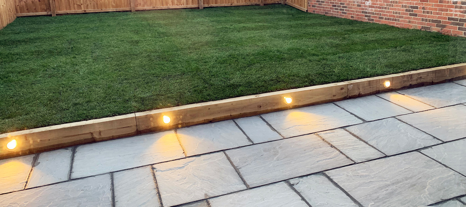
Each of the spotlights has a (supposedly) waterproof T-junction box behind it, which I suspected was the point of water ingress. When I removed the lamps from the fittings, I noticed that most of the fittings were damp inside from either condensation or water ingress - I couldn’t tell which.
I didn’t particularly fancy digging up the grass and pulling the fittings out of the sleepers, particularly given that everything was absolutely soaked after weeks of persistent rain. I isolated the spotlight circuit and awaited warmer weather to tackle the issue properly.
3 Months Later
Having seen more than one case of water ingress into outdoor mains-powered lighting; I decided to replace the outdoor lights with a low-voltage (SELV) solution instead. These are usually 12V DC. These are inherently safer and also less prone to faults due to water ingress.
I struggled to find SELV fittings that would replace the mains GU10 type exactly without a lot of padding around the fittings. Most of them were much smaller and seemed to be designed for embedding in driveways or brick walls. I got thinking on a way to keep the existing fittings, but it seemed the GU10 lamp base is exclusively used for mains applications. I set about changing that…
To KiCAD!
I realise that in some circles this is probably an absolute abomination; but adapters to convert GU10 sockets into MR16 (a 12V lamp cap) sockets are already available. However, these often increase the height of the lamp assembly too much for some fittings.
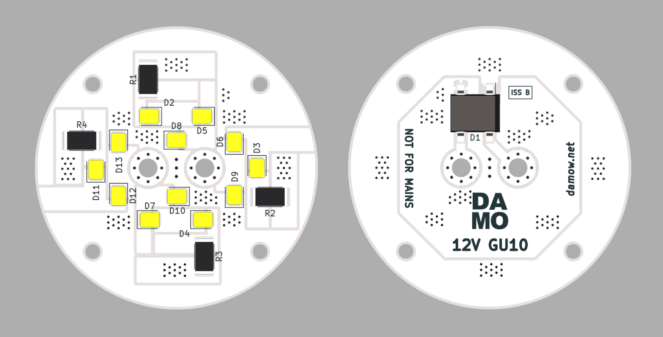
The design is quite simple. Just 4 groups of (3 2835 LED chips in series with a 2512 size current-limiting resistor). At first I designed a more efficient lamp with a switching regulator; but later simplified the design to allow PWM dimming too (which I took advantage of later). Each lamp also has a bridge rectifier (D1) to allow insertion in either polarity (GU10 isn’t polarised, because it’s usually used with AC). In theory this would also mean you could use a 12V AC supply to run the lamps; but they might look a bit flickery.
I also had to come up with a way to produce a GU10 lamp cap with the two locking bayonet pins at home. I looked online at Alibaba and other sites, and the metal “lugs” they use as pins are available to buy; but not accessible in small quantities, and would also be difficult to attatch to the board.
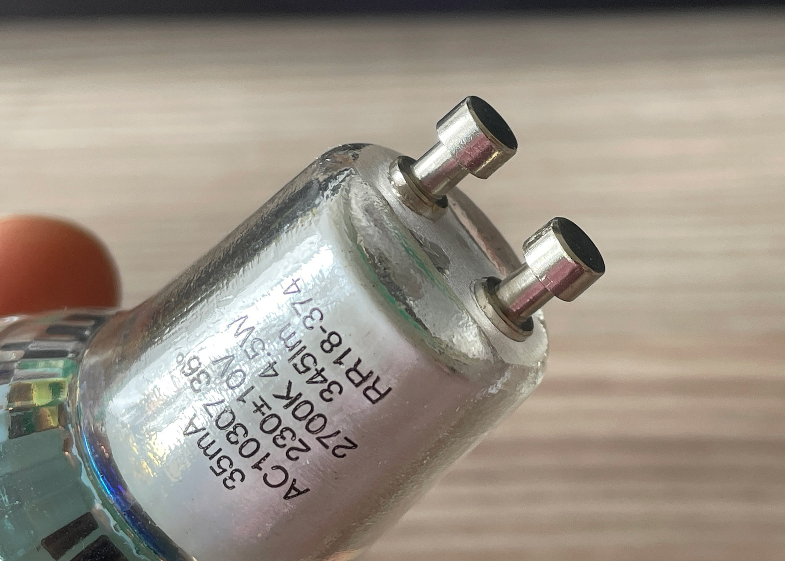
The solution I came up with involves two M3 machine screws. It turns out these are exactly the same size as the lugs used on GU10 lights. Some long machine screws, dome nuts and spring washers to make good contact proved to be an easy (and cheap!) solution.
Not long after sending the board design off to JLCPCB, I was ready to assemble them!
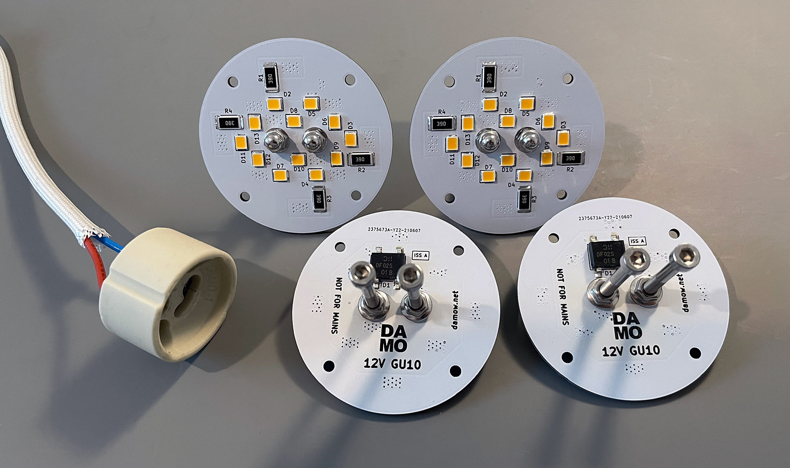
I bought a selection of 2835-size LEDs from Digi-Key in a range of colour temperatures. I ended up fitting the 3000K 150mA 2.95Vf CREE J Series® JB2835AWT-W-U30GA0000-N0000001 LEDs. With 39Ω 2512-size resistors (for a LED current of 50mA) and a total system current of 200mA (~2.4W including power dissipated by the diode bridge), the lamps stay at a sensible temperature and have good light output.
Dim & Dimmer
On the power supply end, I decided to use a standard 12V power supply from Mean Well (HDR-100-12) to power all of the lights (5 on the patio and 4 others elsewhere, a total of 1.8A).
For the patio spotlights especially, I wanted to have some control over the brightness, so I picked up a great little product from a small electronics company in the UK called Abeltronics - their DIM14DIN. It’s a 12/24V PWM dimmer ideal for LEDs. The input for this model is a 0-10V analog input; but they make other models with different input types.
Combined with a Raspberry Pi & Home Automation 8-Layer Stackable HAT, which has a number of 0-10V analog outputs, I was able to tie the lights into HomeKit and have Siri handle requests like “Set the Patio lights to 50%”.
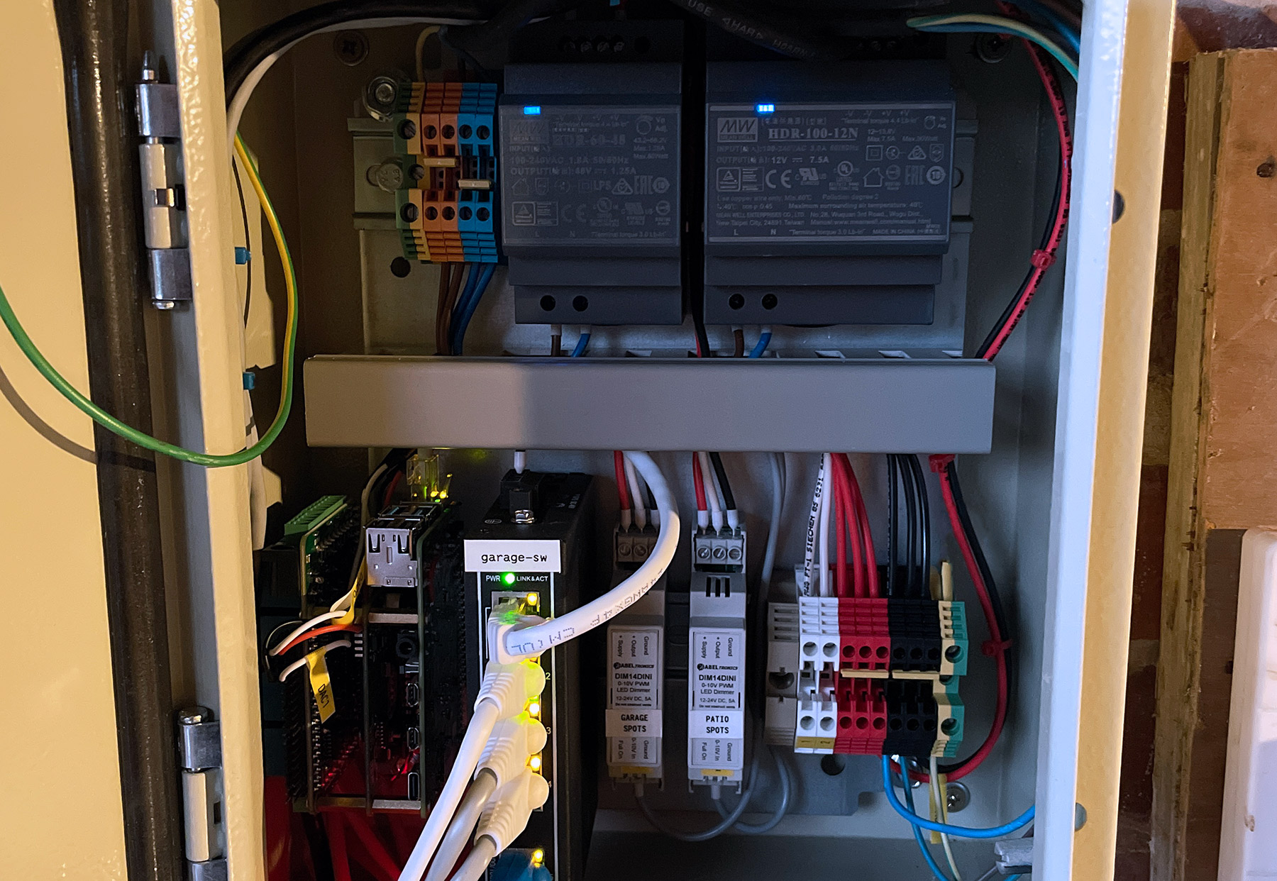
All of this fits quite nicely into a small equipment cabinet in the garage so it’s kept dry and easy to access if maintenance is required.
As ever, all my designs are on GitHub. You’re free to get some boards made yourself, or read-on if you’d like an easier way to get your hands on some…
Want Some?
Something I’ve considered doing for a while is putting some of the things I’ve designed and posted about here up for sale somewhere. I have ~25 of the 12V GU10 lamps so if there’s some demand I may build them up and put them on sale here. Let me know in the comments below if that would appeal to you.