DIY HomeKit
HomeKit is a new-ish feature in Apple’s iOS mobile operating system. It allows you to control various types of devices (called Accessories) from your iOS device.
Introduced in iOS 8, it’s didn’t really make an impact until recently with the launch of iOS 10 and the introduction of the new Home UI. We’re now starting to see some interesting products hitting the shelves that support HomeKit - but they’re not cheap, and, well who wants to buy off-the-shelf plastic-y stuff? So I thought I’d have a go at rolling my own (partially) connected home.
I thought I’d start simple with something that is easy to get going and involves only inexpensive components - a HomeKit temperature sensor.
Collecting the Data
To build a temperature sensor, you have a few options. You could use a standard NTC/PTC impedance-based thermistor-type temperature probe, which are nice and cheap but require an ADC (Analog to Digital Converter) to convert a voltage into a digital value.
Today, there are digital solutions such as the ubiquitous Maxim (formerly Dallas Semiconductor) DS18B20.
These are very common and very powerful digital thermometers. They’re quite precise, low power and it’s easy to interface with. You can have multiple sensors connected to the same bus and they’ll even run in a special parasite power mode where they steal their power supply from the data line, meaning you only need two wires (ground & data) to connect them. They communicate using the 1-Wire protocol, for which there are many libraries available for various platforms (and for which the Linux kernel has built-in support too!).
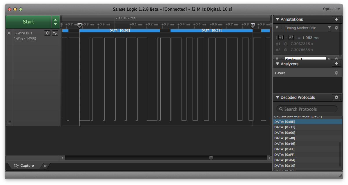
Spying on the communication with the sensor in Saleae Logic. These two bytes contain the temperature value as converted by the sensor. Bonus points for those playing along at home if you can decode the temperature and tell me what it was in the comments! You’ll probably need this 😉
Bluetooth
I decided that I wanted a few temperature sensors, since the temperature in my house can vary quite a bit from room to room. Since the Raspberry Pi can’t be in more than one place at once, and I didn’t fancy trying long-range 1-Wire cabling, I needed a wireless solution.
I liked the idea of a few little DS18B20-based temperature sensors communicating with the Raspberry Pi via Bluetooth from around the house. My Raspberry Pi is a Version 3 Model B V1.2, so already has a Bluetooth chip built right in.
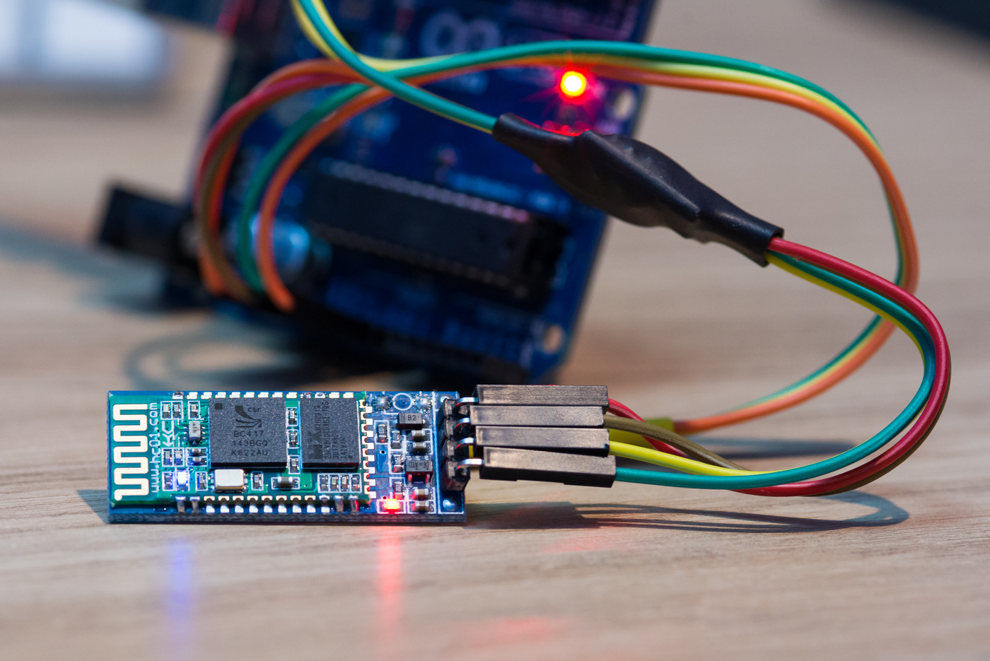
Having trawled around eBay a little, I came across some Bluetooth modules that looked suitable to act as the remote nodes. These seem to come under all kinds of names and descriptions, but essentially they’re CSR (Qualcomm) BC417-based Bluetooth V2.0 devices with some awful Chinese firmware flashed onto them that makes them act as SPP (Serial Port Profile) serial bridges. They usually have some supporting electronics (LEDs, voltage regulators, level converters etc) bodged around them on a kind of motherboard and are typically sold with names like “HC01”, “HC05” and “HC06”. They’re around £3 ($4) each, so hardly break the bank.
I won’t go into too much detail about these modules because there are so many varieties and firmwares floating around the Internet marketplaces that it’s really just a matter of obtaining some and then figuring out which ones you’re dealing with once they arrive.
The specific modules I chose (the “HC-06” variety, but still marked hc01.com with GW-040 on the back, for some reason…) basically act as “slave” devices only - you can’t initiate a connection from them, only to them, but that’s fine for what I need. You pair with them, connect, and send the data, and it transparently emerges at the other end of the tunnel. You can set their advertised bluetooth name by sending them AT+NAMETheNewName and change the pairing pin with AT+PIN12341.
Building the Temperature Sensors
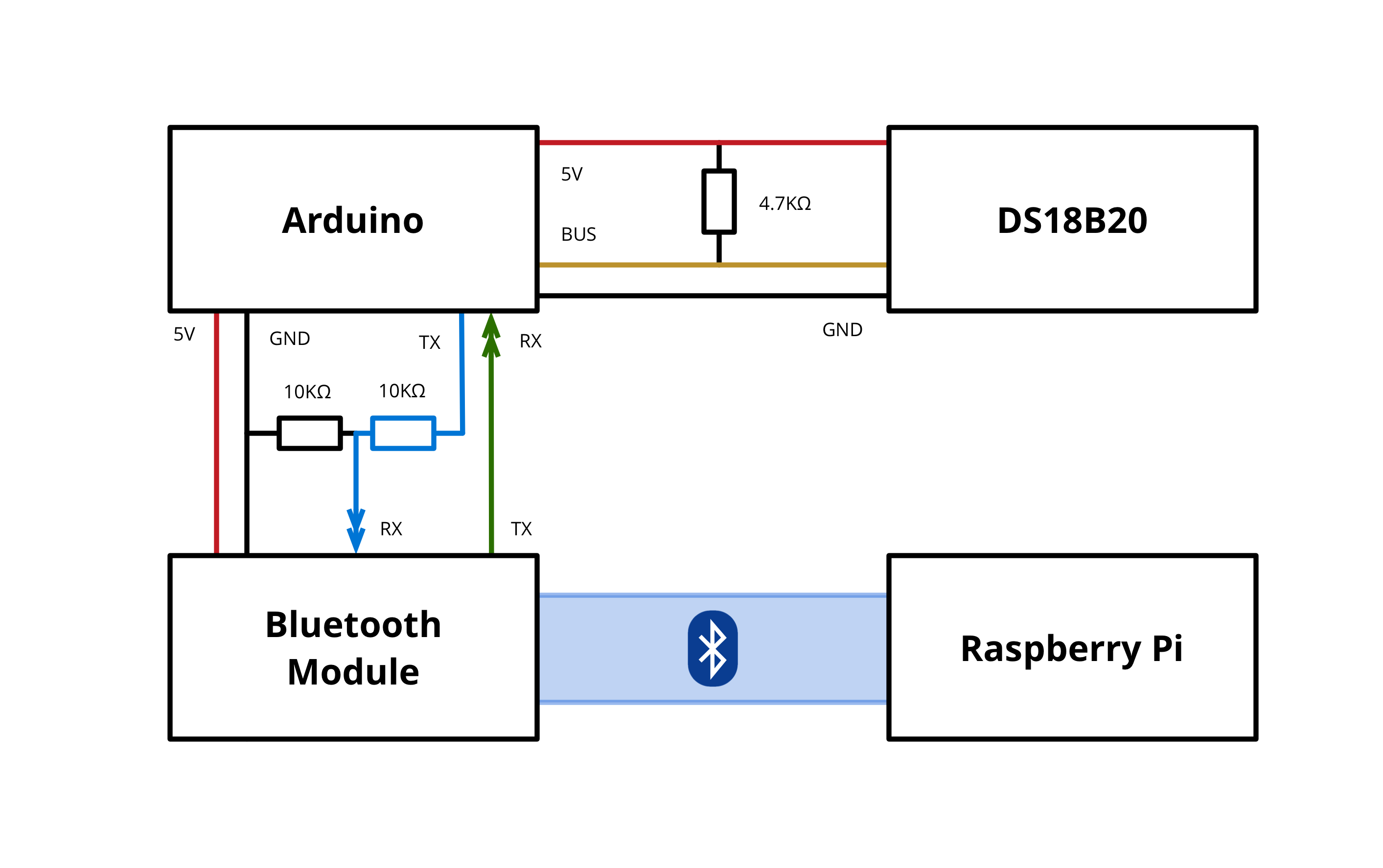
I based the temperature sensors around Arduinos, mainly because I have a bunch of them floating around gathering dust. The wiring is pretty simple - the only passive component required to interface the temperature sensor is a 4.7k resistor to pull the data line up (so, between the data line and the 5V line).
The Bluetooth module is almost as simple. Just a simple potential divider based level converter to bring the TX line (which is at 5V logic level from the Arduino) down to the 3V3 logic level accepted by the Bluetooth module. The other way (TX from the Bluetooth module) is fine, because the Arduino will see the 3V3 high (1) state as high (1) still anyway2.
I wrote a simple sketch that has the temperature sensor perform a temperature conversion every 10 seconds then sends the data as a simple JSON string to the Bluetooth module:
{"temp":24.15}I chose JSON because, well, it’s a standard. I could have just sent the temperature value, but this opens up the ability for the sensors to one day send other values alongside the temperature too.
From there, it’s onto the Raspberry Pi to get the data into HomeKit.
Getting the Data Into HomeKit
The first step to setting up the Raspberry Pi as a HomeKit bridge (which is basically a HomeKit accessory that hides a number of other accessories behind one IP address) was to install Homebridge and any dependencies it requires.
Homebridge is a Node.js application (based around the HAP-NodeJS project) that implements the HomeKit protocol (that is normally supported by accessories bearing the HomeKit label). The project lets you implement your own accessories in Node.js that can become fully-functioning parts of the HomeKit ecosystem and are visible in the Home iOS app.
Thankfully the Homebridge GitHub Wiki has a nice article explaining exactly how to get it installed on a Raspberry Pi.
Next, I wrote some code to listen to the Bluetooth serial ports on the Raspberry Pi and expose the temperature data as HomeKit accessory characteristics. This is basically a Homebridge accessory plugin that listens for temperature updates coming in over a Bluetooth serial port (or any serial port, for that matter).
I’ve created a Git repository containing both the Homebridge plugin and the Arduino sketch I created for this setup.
Then, to get things going, I paired each of my Bluetooth modules with the Raspberry Pi using the bluetoothctl Bluetooth frontend:
$ bluetoothctl
bluetooth> agent on
bluetooth> default-agent
bluetooth> pair 00:11:22:33:44:55
bluetooth> pair 66:77:88:99:AA:BB
Then I created character device files bound to the SPP channels for each of the devices using rfcomm:
$ rfcomm bind rfcomm0 00:11:22:33:44:55
$ rfcomm bind rfcomm1 66:77:88:99:AA:BB
This yields two character device files, /dev/rfcomm0 and /dev/rfcomm1 that represent the two Bluetooth serial ports. These files need to be referenced in the Homebridge’s configuration file (~/.homebridge/config.json):
{
"accessories": [
{
"accessory": "BluetoothTempSensor",
"name": "Temperature 1",
"port": "/dev/rfcomm0"
},
{
"accessory": "BluetoothTempSensor",
"name": "Temperature 2",
"port": "/dev/rfcomm1"
}
]
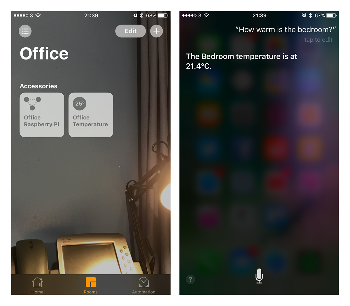
}Once that was done, it was just a matter of starting Homebridge and pairing the “Bridge” device it presents with the Home app on my iPhone and it all came together.
Onwards
Going forward, I’d like to add some more interesting components to my setup. I’ve ordered some isolating relays that can switch mains voltage and some motion detectors that I think I’ll work on next. I’d also like to try and make my remote temperature sensors battery powered by implementing some of the low-power techniques available for Arduino/AVR.
My aim is to build a reasonably-connected home cheaply, using just bits from eBay and electronics suppliers like RS Electronics and Farnell, along with amazing Open Source software like Homebridge and HAP-NodeJS.
Stay tuned for the next installation!
-
Both of these commands need to be sent with no line break or carriage return after the command. The modules interpret any commands after 1 second of idle time, so you need to either type quickly or paste the entire command into the TTY in one go. Eugh. ↩
-
This isn’t ideal, particularly for low-power applications, because while the TX (Arduino) → RX (BT Module) line is high, current is leaking away to ground - not much, but a little (0.25mA in my setup). I’ll be running my sensors from USB ports around the house, not from batteries, so it’ll do for my requirements. ↩