Scantronic 9651 keypad/PC interface idea
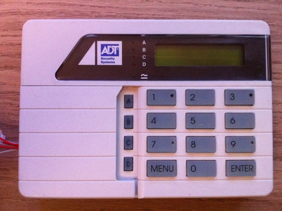
One of the various bits of rubbish I’ve got hanging around is an old Scantronic 9651 keypad (actually a Scantronic 930). For the uninitiated: Scantronic is a range of security alarms manufactured by Cooper Safety. In the security installers industry, they tend to be branded by individual companies that do the actual install jobs; for example, my control keypad is branded by ADT.
Long story short, I’d like to hook this up to my Mac so I could write some kind of emulation software or otherwise use it as a control device. “Why?” I hear you ask, and I retort: “If you are still asking Why? at this point, why are you still reading my blog?”. Onwards with the geekery…
It is my understanding that these keypads function as serial terminals that send keystrokes to, and receive screen updates from the main controller board. Up to 5 keypads can be connected to one controller board to allow control of the system from several different locations around a site. They are to be connected in a daisy-chain or star configuration (I.e. in parallel). This information is quite readily available in the form of the various manuals that Cooper release with their products. The protocol that dictates how the keystrokes and screen updates are communicated is however, a more closely guarded secret.
The headers that I think are associated with the serial communication between the keypad and the controller board are labelled “SIG” and “SRQ”. My initial thought was that the “SIG” pin would convey 1s and 0s as high and low voltage values with the 0V pin. A check with the oscilloscope shows that this isn’t the case. Further investigation shows that during key presses when the keypad is powered up, all the pins maintain their voltages as usual, with no variation at all. Curious.
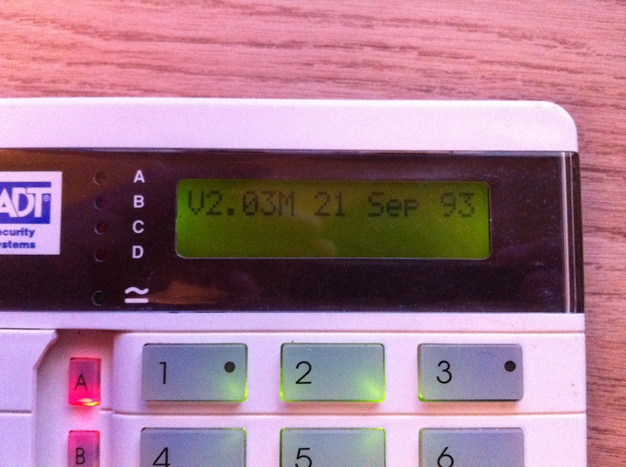
I investigated the behaviour of the keypad without messing with the headers at all. Internally, there are two DIP-style switches that are labelled “PROG” and “TEST”. The “PROG” switch places the keypad in a programming mode (a rudimentary interface allowing the enabling and disabling of the backlight and sounder, as well as the modification of the keypad address). The “TEST” switch places the keypad in a testing mode, flashing all the LEDs in a sequential manner and testing the LCD display. When the keypad is in it’s “normal” mode (I.e. with both the internal switches set to off), it seems to accept 16 keystrokes after powering up, then starts beeping with each keystroke in a way that suggests the keystroke was declined. This behaviour gives me the impression that there is some kind of buffer in effect here. Curiouser.
As a continuation of this thought, perhaps the “SRQ” pin comes in to this. I would theorise that the controller board sends some kind of identifiable pulse unique to each keypad address on a regular basis on the “SRQ” pin - say, every 5 seconds each of the 5 possible keypad addresses are “polled” by the controller board. This would mean that each keypad has 1 second to dump its buffer of keystrokes on the “SIG” pin in a TDMA-style arrangement whereby up to 5 keypads may share one communication medium (in this case, the “SIG” pin). Though of course, there is always the possibility that I am wrong. Another possibility is of course that this keypad is fried. The time in my cupboard under a load of electronic rubbish and quality time with our good friend Mr. Electrostatic discharge might well have finished this guy off. After all, it IS nearly as old as me…
I have an ace up my sleeve here however. I have just won a wonderful like-new Scantronic 9651 Controller board with an additional 930 keypad! Hopefully I will be able to inspect the behaviour of the controller boards respective “SIG” and “SRQ” pins and crack this whole thing wide open, at which point I will of course publish a wonderful blog post detailing all the geeky goodness.
Until then, play safe!