Fun with Flip-Dot Displays
I recently acquired a flip-dot display.
I’ve always loved how these operate. The “analog” update animations and sounds are tactile and refreshing. In an age of instantly-updating glaring LED signs and message boards, I think the appreciation for these beautiful electromechanical works of art is at risk of being lost.
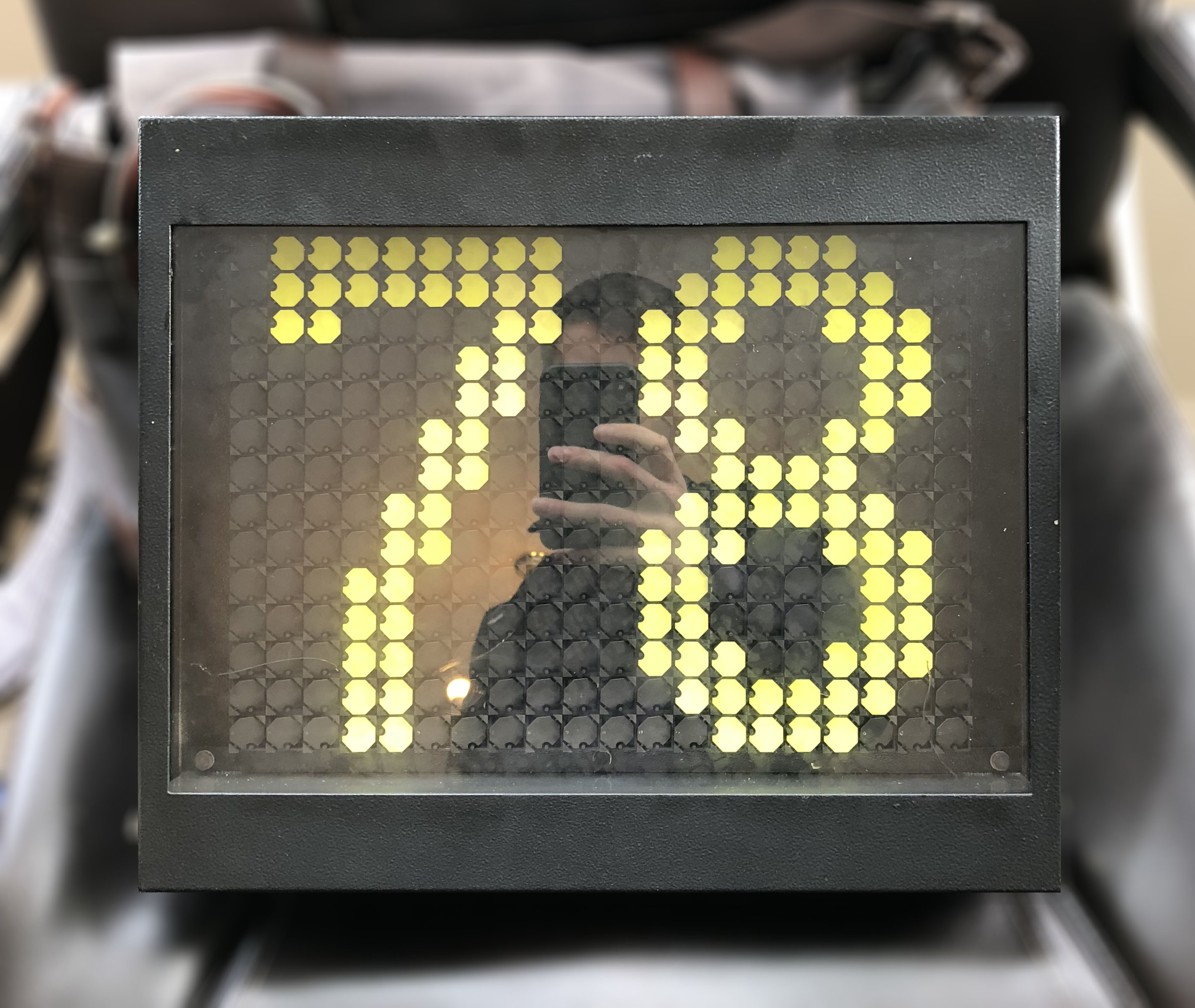
The display is a Hanover Displays R014B 20x14 electromechanical flip-dot display.
Internally, the display has two PCBs. The main dot board PCB has the electromechanical dots and some driver circuitry. The control board has the power supply circuitry (for both the display & the integral LED lighting) and the control circuitry for the display itself.
The control board has a 24-volt DC power input and a two-wire RS-485 control input. The control input uses a proprietary protocol designed by Hanover that I won’t go into in too much detail here - it’s been reverse-engineered by others before1. I have written a basic Node program to talk the protocol just for testing purposes.
Dot Board
The dot board consists of an array of pivoting flip dots. Each has an embedded permanent magnet and sits above a metal U-shape. The metal U-shape has a coil around each “arm”. The display updates dots by pulsing current in one of two directions through the coils.
This alters the field direction in the metal U-shape which changes which side of the permanent magnet is attracted to which “leg” of the U-shaped metal. Each dot is bistable, meaning that once it is set into a state, it will remain in that state until a further state update is made - even if the power supply is disconnected. This also means that the dots always return to their correct position even if they are moved by some outside force.
Internals
My first steps were to reverse-engineer the dot board itself. The circuitry is based mainly on 4000 series CMOS logic circuits so there was no micro-controller magic obscuring the functionality. Firstly, I took photographs of the board and annotated tracks in Photoshop. Continuity testing mode on the meter comes in extremely handy for this.
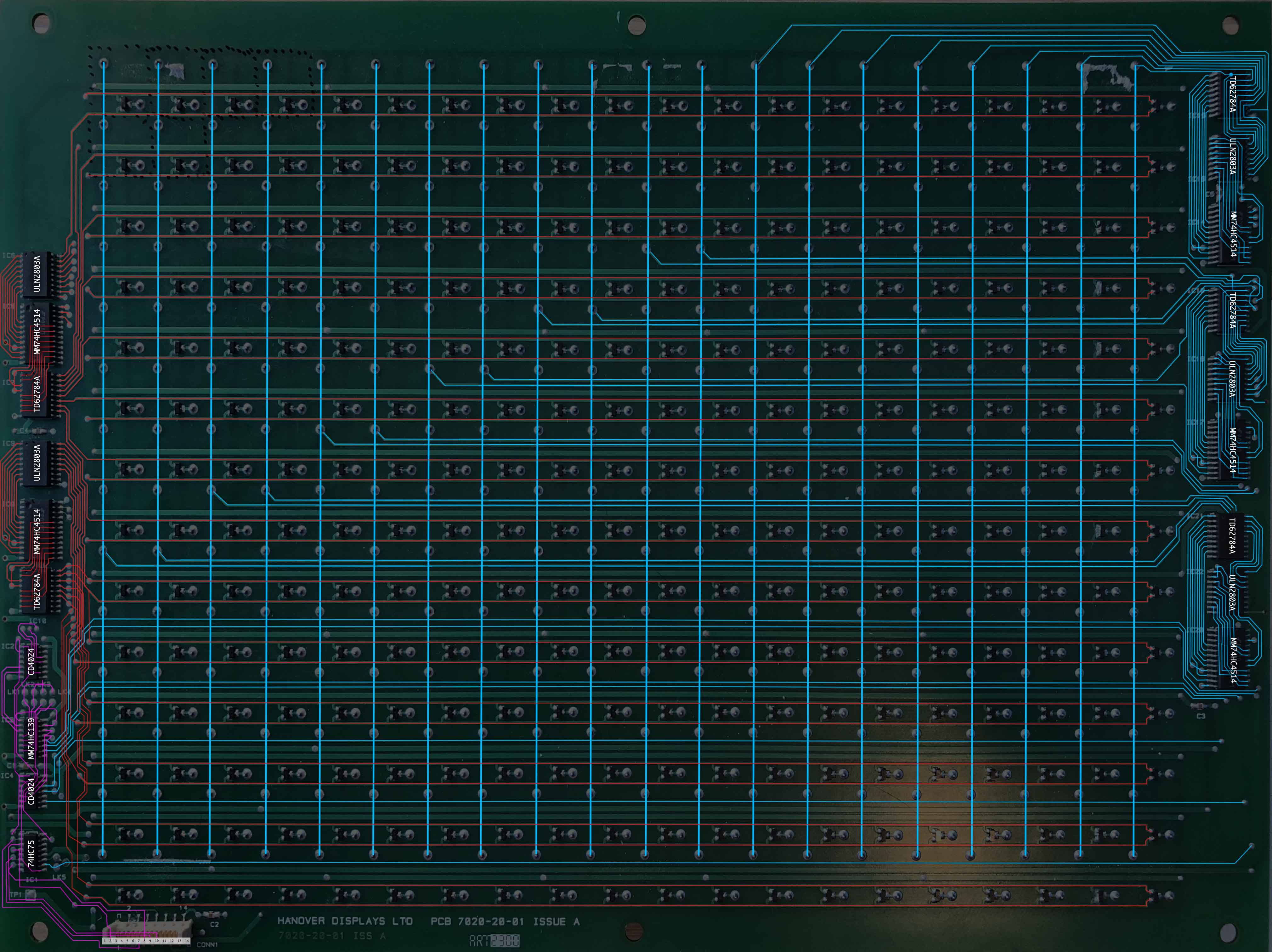
Then, once I’d figured out the basic concepts behind the circuitry, I recreated the circuit as a rough schematic in Upverter:
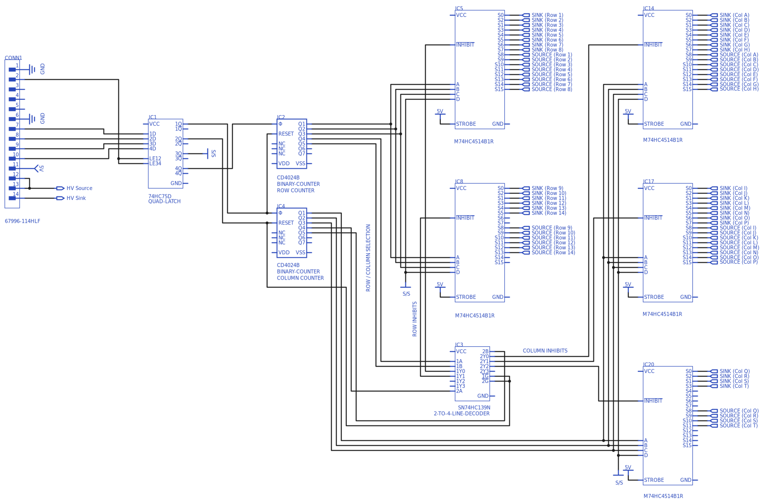
Here’s a brief rundown of how the dot board works. The dot board has two binary counters (CD4024BC) - one to keep track of the current row and one to keep track of the current column. Another input selects whether that dot should be on (yellow) or off (black). A combination of these three inputs selects using line decoders (74HC4514 and 74HC139) a current path for that dot that will either source current (via a TD62784A) or sink current (via a ULN2803A) through the coil.
The control board connects to the dot board via a 14-pin Lumberg MICA14 connector (which took some finding!). The pinout is as follows:
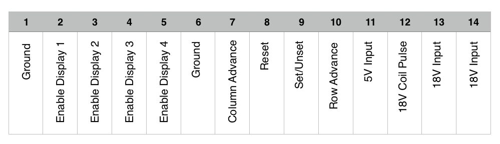
The Enable pins (2 to 5) are used mainly when the display is being used as part of a multi-panel display (for instance, the wide destination blind on the front of a bus).
The Column Advance pin (7) and Row Advance pin (10) increment the Column and Row counters respectively, which select which column and row is being altered.
The Reset pin (8) does just what you’d expect, it simply resets the counters.
The Set/Unset pin (9) selects which way current will be pulsed through the selected coil and thus determines whether the dot will be flipped to the yellow (on) or black (off) side.
The 18V pins (12, 13 and 14) provide the main drive power to change the dot states.
I captured some traces during display updates with my oscilloscope to confirm that my understanding of the dot board operation was accurate.
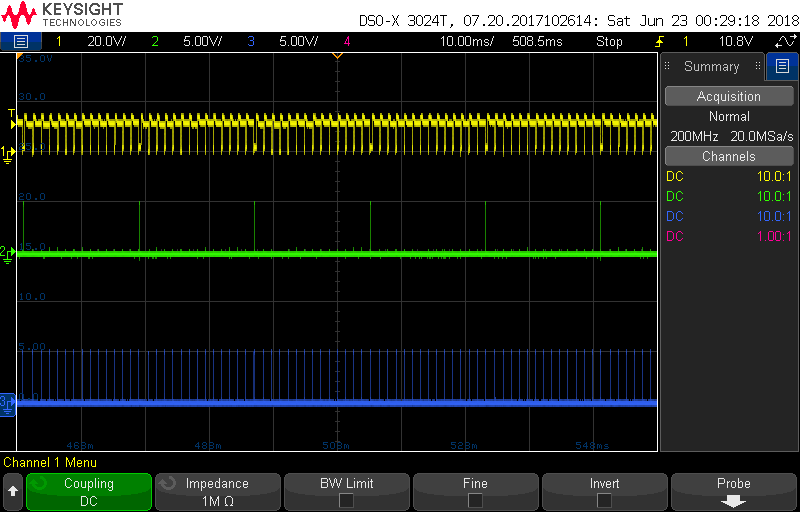
The yellow channel is the 18V pulse input (note the 20V/division setting); green is Column Advance and blue is Row Advance. If you count carefully you can see the 14 rows for each column. A pulse is sent after the address is set up by the Row and Column advance lines.
Measuring Up
While experimenting with the original control board, I noticed some interesting behaviour when the system is first powered up. When power is first applied, the dot board will show a single horizontal line, then a single vertical line, then clear.
After watching this process a few times with the scope, I reasoned that the controller does not know the size of the connected display, therefore it must be measured at each power-up. The controller advances along the columns and sends a pulse - if current is observed to flow, a coil must be connected at that position; if not, the edge of the display has been reached. The same process is repeated for the vertical dimension. Indeed, this same process is repeated for each of the four Enable lines to detect other connected displays.
Building a Controller
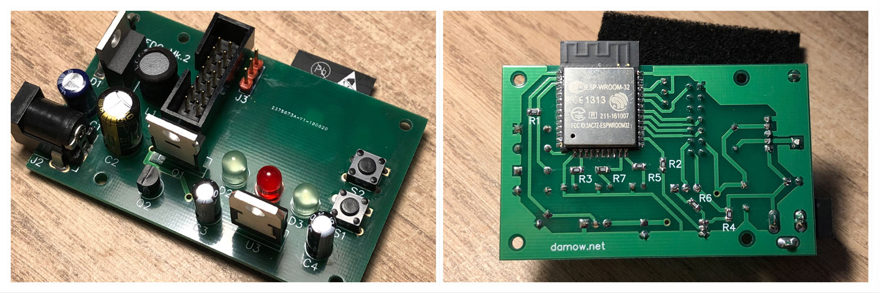
I set out to build a circuit to replace the control board. Essentially all I needed to do was replicate the CMOS logic signals to control the binary counters and provide the 18V pulse to drive the dot coils.
I went with my favourite micro-controller, Espressif Systems’s ESP322. For the 18V pulse supply, I chose a suitable BJT/MOSFET combination. The ESP32 needs a 3.3V power supply and the dot board needs 5V in addition to the 18V coil supply. I used a TI LM2576-5.0 switching regulator to buck an 18V input down to 5V, then a simple linear regulator to further reduce the voltage to 3.3V for the ESP32. This way the whole setup can be powered from a standard 18V DC “brick” power supply.
After some experimentation and prototyping of the circuit on breadboard, I designed and then made a PCB.
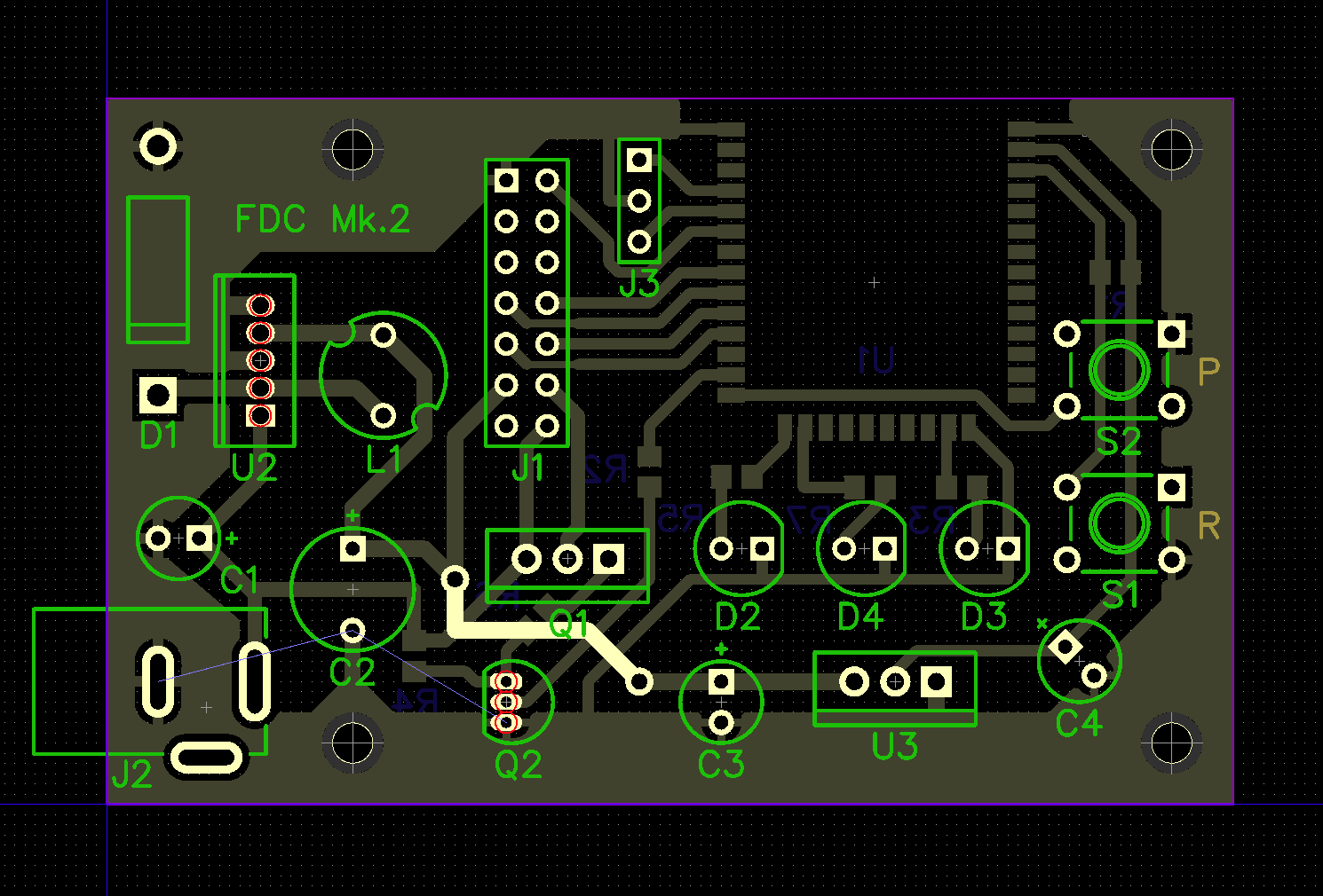
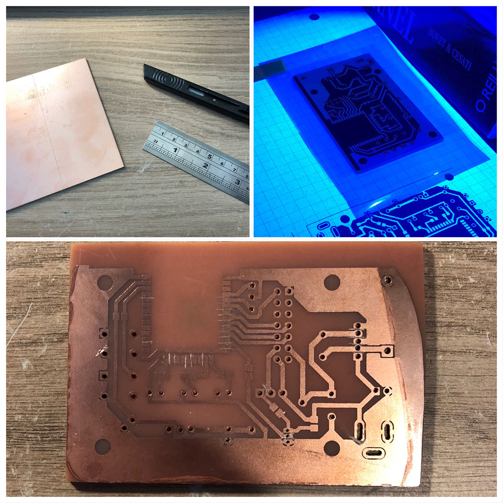
This was an interesting process, and not something I’ve done at home before. I used the dry resist film technique and etched with Ferric Chloride. This isn’t easy at home. Even on my final board, the dry resist film didn’t stay down completely at the edges and some etchant was able to get underneath and eat away at the ground fill. The boards are also very difficult to solder owing to the lack of solder mask. After some experimentation and (initially limited) success, it wasn’t pretty, but I’d produced my first working PCB!
The PCB worked great and the firmware I had written to test my design during the breadboarding stage of prototyping worked straight away. I wrote some more firmware for the ESP32 to render a basic 5x4 character set and wrote some test code to put the controller circuit to work. I even made some optimisations that meant only the required dots were pulsed, which improved the update rate considerably.
Getting it Made
I wasn’t entirely happy with the quality of the home-made PCB though, so I sent my design off to JLCPCB in China for a more professional rendering. I had the boards incredibly quickly - just a week later, and they really looked the part.
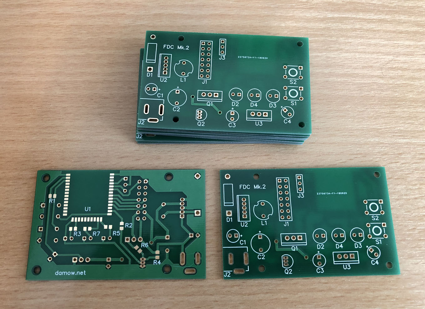
Soldering was far easier on boards with a proper solder mask, particularly for the fiddly SMD stuff. I think if I did a respin of this board I’d add some more buttons and perhaps a proper RTC.
I have 9 more boards that I can build up, so if anyone would be interested in obtaining one of these, drop me an email or leave a comment below! Of course, the Gerber files and BOM for the PCB are both available in the GitHub repository for the project.
The displays themselves are pretty easy to get hold of, at least in the UK. I got mine from psvautomobilia on eBay for about £95.
I’ll leave you with a video of the controller driving the display really fast. I’ve implemented this scrolling text demo to the GitHub repository for the project.
-
John Whittington, “Adventures with Flippy the Flip-Dot Display” https://engineer.john-whittington.co.uk/2017/11/adventures-flippy-flip-dot-display/ ↩
-
I checked the datasheets for the CMOS ICs used and 3.3V was ample to be considered high by the CMOS chips on the dot board so no level-shifting circuitry ended up being necessary. ↩